
I am trying to reconnect the vac lines on my 83 inline six, but I need to know where the two vac lines to the air breather come from and where the vac lines to the purge valve go to. Any pics or directions would be helpful.

Vac Lines 83 Inline Six
Started by
Straight6
, Sep 12 2004 12:39 PM
15 replies to this topic
#2

Seabronc
-

- Moderators
-

- 683 posts
F-Series Commander
- Location:North of NYC
Posted 12 September 2004 - 08:45 PM
the vacuum line to the air cleaner comes directly from main vacuum. You can tap into that where the break booster connects. Usually there is a multiple tap plug in the intake.
The purge vacuum usually comes from the center port on the Vacuum control Valve, (also called a Ported Vacuum Switch, Ford isn't too consistant with terms), located on top just infront of the hose going to the radiator. It should be a 3 port vacuum switch , probably yellow. The top port will probably have a filter plugged into the connector. The source of vacuum is usually from the same port on the carb as the EGR. If the engine hasn't been changed, there should be an emissions sticker on the radiator support, passenger side showing a schematic of the vacuum system for that truck. The EGR port is the one on top of the carb to your left when looking at it from the front of the truck.
I am attaching a picture of an emissions calibration sticker as an example, it is for my engine, 351W 4bbl.
Red = Main vacuum
White = EGR source vacuum
Orange = Heat Control Valve vacuum
Black = a misic use color
Pink = Air inject system
The other thing will be getting the right temp PVS / VCV. Usually the EGR one will be Blue, The Heat Control - Green, and the Purge Control - Yellow.
If I can be of further assistance, let me know.
"I know you think you know what I said, but what you need to know is, I did'nt say what I meant"
#3
Seabronc
-
- Moderators
-
- 683 posts
F-Series Commander
- Location:North of NYC
Posted 12 September 2004 - 08:47 PM
Here is a picture of my engine showing the location of the VCV for the purge control.
Good luck
Good luck
"I know you think you know what I said, but what you need to know is, I did'nt say what I meant"
#4
Seabronc
-
- Moderators
-
- 683 posts
F-Series Commander
- Location:North of NYC
Posted 13 September 2004 - 04:00 AM
OK, the vacuum lines on my air cleaner are hooked up as follows nad probably are the same on yours. If you look at the attached picture, top left, you will just see the connection for main vacuum (hose comming out the top fitting of a plastic device, on the side of the air cleaner, which is called a TVS (Temperature Vacuum Switch, white plastic right angle connector). From the botttom connection of the TVS to what is called a CWM (Cold Weather Modulator) mounted on the bottom of the air cleaner, a all metal device. From the CWM to the vacuum motor on the top of the intake scoop. The function is to controll the temperature of the air comming into the intake in cold weather. The vacuum motor opens and closes a flap that mixes air from the shroud around the exhaust manafold with incomming air from the scoop. This is only used in the winter. At other times of the year the incomming air temp will be warm enough to cause the flap to be open completely.
Good luck,

Good luck,
"I know you think you know what I said, but what you need to know is, I did'nt say what I meant"
#5
Straight6
-
- Members
-
- 58 posts
F-Series Mechanic
Posted 13 September 2004 - 05:25 PM
O.K. the air cleaner vac lines are finished but I am still having trouble with the purge valve. On my motor the vcv is a four tier piece and is colored blue and it does have a vac line going to the purge valve but there are two others one going to the carb (large line) and the second a small line that is not connected to anything. So where does the second small line go to?
Seabronc,
Nice motor, how do you keep it so clean? I just rebuilt mine, painted it blue and it still does not look like yours. Nice job.
Seabronc,
Nice motor, how do you keep it so clean? I just rebuilt mine, painted it blue and it still does not look like yours. Nice job.
#6
Seabronc
-
- Moderators
-
- 683 posts
F-Series Commander
- Location:North of NYC
Posted 13 September 2004 - 06:37 PM
I can't say for sure. I have to go near my local friendly auto Recycler tomorrow. I'll see if he has a 6 that is still hooked up or has an emissions sticker I can photograph.
The 4 port VCV is nothing more than two 2 port VCV's stacked on top of each other. When cold, no vac is transferred thru the port. A blue one should allow vac when the coolant warms up to 125f. Is that blue one located where my yellow 3 port VCV is located? I have never seen a calibration that used a 2 port VCV to operate the purge, but then I haven't seen everything yet . The purge normally uses a 3 port VCV so it has vacuum when starting until the engine warms and then dumps the purge valve to the atmosphere. You should see that on the digram I attached previously. The 2 port VCV usually controls the EGR vac and is sourced from the top passenger side port on the carb.
As you can see on the schematic, my purge valve has source on the bottom purge in the middle and a filter on the top port. That makes the purge operate untill 160f and then the purge control line is dumped to atmosphere.
Anyway, I'll let youknow what I find tomorrow if anything.
Just found a picture of my calibration when I was first rebuilding the vacuum harness. It shows the relationship of the VCV's, ignore the lines hooked up to them, some of them ar not correct. Just an example of who does what. The one on the left (blue) controls the EGR sourced from the EGR port on the carb white line. The (green) controlls the Heat Control Valves (one on the intake one on the exhaust pipe hookup). The (yellow) controls the purge ( all hooked up wrong in this picture. On the 302 for example two of them are located on the back side of the intake manafold, so a six might have them spread out in some other location.
More tomorrow, I hope.
The 4 port VCV is nothing more than two 2 port VCV's stacked on top of each other. When cold, no vac is transferred thru the port. A blue one should allow vac when the coolant warms up to 125f. Is that blue one located where my yellow 3 port VCV is located? I have never seen a calibration that used a 2 port VCV to operate the purge, but then I haven't seen everything yet
. The purge normally uses a 3 port VCV so it has vacuum when starting until the engine warms and then dumps the purge valve to the atmosphere. You should see that on the digram I attached previously. The 2 port VCV usually controls the EGR vac and is sourced from the top passenger side port on the carb.As you can see on the schematic, my purge valve has source on the bottom purge in the middle and a filter on the top port. That makes the purge operate untill 160f and then the purge control line is dumped to atmosphere.
Anyway, I'll let youknow what I find tomorrow if anything.
Just found a picture of my calibration when I was first rebuilding the vacuum harness. It shows the relationship of the VCV's, ignore the lines hooked up to them, some of them ar not correct. Just an example of who does what. The one on the left (blue) controls the EGR sourced from the EGR port on the carb white line. The (green) controlls the Heat Control Valves (one on the intake one on the exhaust pipe hookup). The (yellow) controls the purge ( all hooked up wrong in this picture. On the 302 for example two of them are located on the back side of the intake manafold, so a six might have them spread out in some other location.
More tomorrow, I hope.
"I know you think you know what I said, but what you need to know is, I did'nt say what I meant"
#7
Seabronc
-
- Moderators
-
- 683 posts
F-Series Commander
- Location:North of NYC
Posted 15 September 2004 - 02:05 PM
By the way, you have not answered my queston about the presents of an emissions control sticker on your passenger side radiator support. If you do have one, post a picture of the calibration and I can be more accurate inmy response.
OK, found a calibration that infact uses a 4 port VCV to control purge. Actually it only uses two of the ports the other two ports control the EGR vacuum. The calibration is not for your engine but reasonable information can be drawn from it. The top two control the vacuum to the distributor. The bottom two control vacuum to the Purge Control Valve (Purge CV) (not to be confused with the oil breather PCV), this is the valve near the emissions canister .
First part of a 2 part answer.
Connections from the Purge CV, as viewed from the top of the unit (flat round cap);
1. Center small top port connects to the VCV (2nd port from the bottom)
2. Bottom center port connects to a large port on the carborator spacer (using fuel grade line).
3. Right port connects to a T. From the T one line goes to the carbon canister and the other goes to a Thermal Vent Valve (TVV) and then on to the Bowl Vent.
Picture of the Canister Purge Valve attached.
Back at the VCV, the bottom port gets vacuum from the carborator spark port.
"I know you think you know what I said, but what you need to know is, I did'nt say what I meant"
#8
Seabronc
-
- Moderators
-
- 683 posts
F-Series Commander
- Location:North of NYC
Posted 15 September 2004 - 02:28 PM
" OK, found a calibration that infact uses a 4 port VCV to control purge. Actually it only uses two of the ports the other two ports control the EGR vacuum."
This should read:
" OK, found a calibration that infact uses a 4 port VCV to control purge. Actually it only uses two of the ports the other two ports control distributor vacuum." in the calibration that I am looking at.
I need a response to my question before I attempt to describe the connection of top two ports of the VCV.
Infact the more pictures you can show me the better.
"I know you think you know what I said, but what you need to know is, I did'nt say what I meant"
#9
Straight6
-
- Members
-
- 58 posts
F-Series Mechanic
Posted 16 September 2004 - 06:30 PM
There is a calibration sticker on the radiator support and I have traced most of it but the purge is not clear to me and the air breather vacuum is not shown. I will get a picture of the engine and sticker on Saturday and upload it and let me say, if I haven't yet, that I appreciate your help. Most of the vacuum lines on this engine have melted the ones that were not are hooked up wrong and that is why I am having so much trouble.
#10
Seabronc
-
- Moderators
-
- 683 posts
F-Series Commander
- Location:North of NYC
Posted 17 September 2004 - 05:02 AM
No problem and you're welcome. Do me a favor, email those pictures to me at [email protected] that way I can use my photo processing program to get a close up look at them.
"I know you think you know what I said, but what you need to know is, I did'nt say what I meant"
#11
Seabronc
-
- Moderators
-
- 683 posts
F-Series Commander
- Location:North of NYC
Posted 22 September 2004 - 07:10 PM
Straight6, how did you make out?
Did you get my email about your pictures. For some reason all I gor was blank pages. Send them to [email protected] maybe hotmail didn't like them for some reason.
Did you get my email about your pictures. For some reason all I gor was blank pages. Send them to [email protected] maybe hotmail didn't like them for some reason.
"I know you think you know what I said, but what you need to know is, I did'nt say what I meant"
#12
Straight6
-
- Members
-
- 58 posts
F-Series Mechanic
Posted 27 September 2004 - 06:25 PM
Seabronc,
The pictures I sent to you were large and that might be reason you did not get them. I bought some emission line and plastic elbows and followed the digram on the front of the truck I will let you know what happens.
On the air breather which side of the small metal valve does the vac line coming from the vac tree go to the side with clamp teeth or the side without?
#13
Seabronc
-
- Moderators
-
- 683 posts
F-Series Commander
- Location:North of NYC
Posted 27 September 2004 - 08:41 PM
The route shoud be from the vacuum tree on the intake manafold to the top port on the TVS which is on the side of the air cleaner, from the TVS bottom port to one of the ports on the CWM on the bottom of the air cleaner, (port not important), and from the other port to the Vacuum motor on the scoop.
It occurs to me that you might not have both of these devices on your air cleaner, is that true in your case?
Do you have them both or just one of them ?
If you only have one, is it on the side or bottom?
The CWM is all metal and mounts inside of the filtered air area with only two tips sticking thru the bottom of air cleaner housing to the outside with.
The TVS is plastic and mounts on the side with a clip holding it from the inside.
If that doesn't make sense I'll take a picture and post it.
If you follow the diagram, you should do OK with the other lines. They show the heat sensitive part of the PVS facing up for some dumb reason, (the dark sort of triangular shaped part, that is the bottom of the valve).
Good luck,
"I know you think you know what I said, but what you need to know is, I did'nt say what I meant"
#14
Straight6
-
- Members
-
- 58 posts
F-Series Mechanic
Posted 28 September 2004 - 01:43 PM
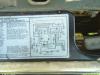
The TVS is on the right hand side of the air breather looking at it from the front of the truck. The CWS is on the under side of the air breather lid, there is nothing on the bottom of the air breather. According to the vac diagram the lower vac line of the TVS runs to a vac port on the left side of the carberator. The top outlet of the TVS supplies two vac lines one pink the other black. The black lines goes to the VCV at the front of the truck the other runs the the air or pollution pump also at the front. I would gladly send you a pic of this just to make sure I am doing this right but I have taken three pictures with a digital camera and can't get a sharp image but I will try to post it here.
Attached Thumbnails
#15
Seabronc
-
- Moderators
-
- 683 posts
F-Series Commander
- Location:North of NYC
Posted 29 September 2004 - 04:24 AM
OK, I have cptured the picture and am in the process of trying to read it and compare the fuzzy stuff to things I recognize. I'll do another post later today.
"I know you think you know what I said, but what you need to know is, I did'nt say what I meant"
#16
Seabronc
-
- Moderators
-
- 683 posts
F-Series Commander
- Location:North of NYC
Posted 29 September 2004 - 02:52 PM
OK, this is much better. I think I figured out everything on the fuzzy picture. We can forget most of what I previoulsy told you.
VACUUM LEVELS
Most of the ports at the carb are at the bottom or on a spacer under the carb and are nearly the same level as the place where the vacuum tree is tapped into the manafold. Also, the order of the ports around the carb is usually the same as shown on the schematic. The port marked E (or EGR port) is tapped of high on the carb which gives a different vacuum signal than main vacuum.
E port is weak @ idle, strong @ cruise, weak @ Wide Open Throttle. Ports under the carb are strong @ idle and slowing, weak @ WOT
Lets take each system on it's own;
1. Your Air Cleaner air intake - From the vacuum tree mounted on intake manafold, (left side of motor); to the A/CL bimet ( this device is all metal and should be mounted inside air cleaner tray, some where internal of the filter,it controls the vacuum motor based on intake air temp); to a VRDV (Vacuum Retard delay Valve) (P/N 9E897) ( for gradual application or relief of the vacuum signal) dark side connected toward the vacuum motor for the Air Cleaner Duct Valve (A/CL DV).
2. Distributor vacuum control - from vacuum tree to a Vacuum Check Valve (P/N 2A197) (Vacuum Check Valve)(hooked in just as shown, dark side toward distributor) from check valve to a T, then from the carb S (spark) port to the other side of the T at the distributor.
3. EGR control - from E port of carb (mentioned above) to VCV bottom port, from second port up to the EGR valve.
4. Evaproative Emissions Control - from main vac port at bottom of carbto a T or Y, to 3rd port up on VCV. From top port on VCV to a T or Y, to the top port on the CPV (Canister Purge Valve).
From the Bowl Vent on the carb fuel bowl to what looks like a TVV (Thermostatic Vent Valve)(this can be either an electrically controled valve or a vacuum controlled valve, if it is not electrical, there should be a main vac connection to the bottom), from there to the large port on the CPV. From tyhe other end of the large port to the canister. From the bottom port on the CPV to (usually a port on the carb spacer).
5. Thermactor Air Control - From the Air Bypass Valve (either mounted on the air pump or close to it) to a VDV (Vacuum Retard Delay Valve)(installed as shown light side facing the TVS dark side facing the Air BPV) to T on TVS. There is also what appears to be a check valve between a T on the TVS and the top port of the VCV.
Note: Both of the delay valves in the schematic appear to me to be VRDV's, if not let me know. I can't make our any of the stuff by the canisters, but one swould be a connection to a furel tank vent line at what looks similar to a Positive Crankcase Valve which is usually connected at the base of the carb also.
Any questions or if I have not read the valve designations on the schematic correctly, let me know.
Good luck,
"I know you think you know what I said, but what you need to know is, I did'nt say what I meant"
Reply to this topic


0 user(s) are reading this topic
0 members, 0 guests, 0 anonymous users

